language

Company:Guangdong PENGLAI Intelligent Equipment Co.,LTD
Factory Address:403B, No.99 Qiaocheng East RD,Nanshan District,Shenzhen,Guangdong ,China
Factory ADDRESS:St George Industrial Park,XinYu Road,ShaJing Town,Bao'an District,Guangzhou City,China
Contact:Jack Du
Cel:+86-15811882441
Phone:+86-755-86718316
Fax:+86-755—25417648
Email:penglaipacking@gmail.com
Email:postmaster@penglaipacking.com
Skype:turnanewleaf
Website:www.penglaichina.com
www.youtube.com/user/penglaichina


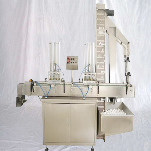
Semi-Automatic Aerosol Filling Machine model YX-ASF500 three in one spray cans filling sealing propellant equipment

Illustration of three in one aerosol cans filling-sealing-gas propellant equipment


● This machine is applied to filling such mediums as compress air,hydrocarbon mixture .Freon,DME, Nitrogen,and Carbon Dioxide and so on . It can produce various aerosol products.
● Filling system newly applied for air compressor equipment, are suitable for dosing filling any kinds of viscosity. No need to configurate a paste filling machine, can save lots of money.
● It can continuously complete gas blowing,feeding,filling,sealing automatically.With the original technical design, it is easy to operate saving time and effort.
● German PTFE seals, wearing-resistant, long lifetime up to more than 5 years.
● Its filling end is controlled separately, no discharging without filling;It is sealing with high quality for adopting oriented-sealing; The way of the oriented inflation in the charging end is accurate and efficient with minimal gas consumption.
● This machine is in advanced level of the same industry at present. It have been exported to Europe, America, Africa, southeast Asia. It's the best choice to set aerosol factory
Technical parameters of aerosol spray cans filling machine:
Model YX-ASF500
Filling volume(ml): 20-750ml(specification can be made by request);
Filling accuracy: ≤±1%
Gas volume(ml): 20-450ml
Gas accuracy: ≤±1%
Sealing accuracy: ≤±1%
Working Pressure: 0.65-1.0MPa
Available valve: 1”(25.4mm)
Production capacity: 5000-6000cans/day
Maximum air consumption: 0.8(m3/min)
Applicable aerosol can diameter: 35-65 (mm)
Applicable aerosol can height: 80-350(mm)
Packing dimension and weight:
Filling machine : 1000*590*1590mm 180KG
Booster pump : 500* 450*600mm 38KG
Manual instruction for model YX-ASF500 deodorant aerosol sppray cans filling sealing propellant machine 3-in-1 filler equipment perfume
The machine model YX-ASF500 constitutes three parts: 1. Section I: Operation Manual of LG Series Semi-automatic Filling Machine
2. Section II: FG1 Semi-automatic Aerosol Can Sealing Machine
3. Section III: PG Series Semi-automatic Propellant Filling Machine
As below there is the basic information for three parts one by one in details
Section I: Operation Manual of LG Series Semi-automatic Filling Machine
I. Function and Features
LG series semi-automatic filling machine has fully absorbed the advanced filling machine technology from the Swiss Pamasol Company, with high filling speed, accurate filling volume, high repetition precision, reliable sealing performance, strong anti-corrosion ability and simple maintenance requirement. The machine is widely used for quantitative filling of aerosol products and other liquid mediums.
II. Major Technical Specifications
|
Model |
YX-ASF20 |
YX-ASF50 |
YX-ASF100 |
YX-ASF200 |
YX-ASF500 |
YX-ASF600 |
|||
|
Maximum Filling Volume (ml) |
20 |
50 |
100 |
200 |
500 |
630 |
|||
|
Repeat Filling Accuracy |
±1.5% |
±1.0% |
|||||||
|
Applicable Can Model |
Height (mm) |
50~160 |
60~350 |
||||||
|
Diameter (mm) |
16~60 |
20~100 |
|||||||
|
Working Air Pressure (Mpa) |
0.45~0.7 |
||||||||
|
Maximum Air Consumption (l/min) |
40 |
50 |
100 |
||||||
|
Production Capacity (can/h) |
1200~1500 |
800~1200 |
|||||||
|
Outer Size (mm) |
900×500×1500 |
||||||||
|
Weight (kg) |
|
|
|
|
|
|
|||
III. Basic Structure and Principle

Shown by the pneumatic principle in Diagram 1.1 and 1.2, LG series semi-automatic filling machine is comprised by filling head, content measurement device, and pneumatic component. Its working procedures are shown as follows: firstly, the liquid content will be pumped out from the containers, into the measurement device, and then adjusting the indicator drum to quantify the content. Place the aerosol can on the operation platform of the machine, push down the “inching” pedal value K1 to reverse the two-position, five-way and dual-air reversing valve V1; when the lower chamber of the small cylinder in the filling head inflows air, open the filling head to start the filling operation; meanwhile, the upper chamber of the cylinder in the measurement device will inflows air, push the quantified content in the feeding cylinder of the measurement device into the filling head and then press the content into the aerosol can (Attention: content will spray out if there is no can placed in position.) After the filling operation is completed, the piston in the upper cylinder of the measurement device will press down the control valve K2 in the connection plate, controlling the air impeder to reverse the two-position, five-way and dual-air reversing valve V1. As for this, the lower chamber of the upper cylinder in the measurement device and the upper chamber of the small cylinder in the filling head will inlet air, restoring automatically and waiting for the next filling operation.
IV. Installation, Setup and Operation
1. Install the machine on flat and solid ground and adjust the screws at the feet of the operation platform to stabilize the operation platform on a horizontal level;
2. Connect the air supply to the entrance of air source jointer of the filling machine;
3. Setup of filling volume: before setup, it is a necessity to turn off the pressure relief valve at the air source jointer of the filling machine and to wait the compressed air in the machine to be emptied; or to pull the manual pipe air evacuation valve on the side of the measurement device to the evacuation position for air evacuation; turn the indicator drum in anticlockwise direction will increase the volume, and in clockwise direction will decrease the volume. When getting the required filling volume, turn on the pressure relief value to restore the pressure to 0.45~0.7Mpa; or to restore the manual air release valve on the side of the measurement device. On this basis, repeat the filling operation, until getting the needed filling volume.
4. Setup of filling head height: firstly release the lock-screw on the side of the slide holder and turn the hand wheel to adjust the height of the slide holder. In according with the height and size of different cans, the filling head shall be adjusted to let the cans go in the go out freely. In the meanwhile, the filling head shall be close to cans as much as possible. After the adjustment, fasten the lock-screw on the side of the slide holder.
5. Setup of the position of aerosol cans: firstly, release the fastening screws of the two positioning block on the operation platform; adjust the position of the block to ensure the aerosol cans and the filling head are homocentric. Then, fasten the screw again.
6. Setup of running speed: liquid mediums of different viscosity have different requirement on filling speed. Before adjustment, firstly, tighten the one-way throttle valve on the side of the measurement device, push down the pedal valve (inching) to do a test filling; slowly release the one-way throttle valve during the operating; on the premise of ensuring that the volume of each filling complies with the allowable error range with proper operation speed and stable running, fasten the one-way throttle valve.
7. Check the above adjustment procedures and then start the filling operation. Place the aerosol can between the two positioning blocks and being close to the positioning blocks; press down the (inching) pedal valve K1 to complete the filling. During the adjustment process, if the air cylinder can not be restored to the initial position, we may use button K3 in front of the operation platform for reposition. Attention: during adjustment and operation, if abnormal situation occurs, please restore the machine by pressing button K3. After finding and eliminating the fault, the machine can be started again.
V. Fault Analysis and Removal
|
Faults |
Causes |
Solutions |
|
No Reaction after Stepping On the (Inching) Pedal Valve |
1. Air leakage of mechanical control value in connection plate of the measurement device, and the outlet pipe always contains air. 2. Button value K3 impeded or air leakage 3. Two-position five-way dual-air reversing valve V1 impeded or blocked. 4. Shuttle valve impeded or failure |
1. Replace the sealing ring or spring inside the mechanical control valve 2. Wash or replace the button valve K3 3. Wash or replace the two-position five-way dual-air reversing valve 4. Wash or replace the shuttle valve |
|
Machine restoration failure, even with button valve pressed |
Pedal valve impeded or leakage |
1. Replace the sealing ring inside the pedal valve 2. Replace the spring inside the pedal valve 3. Replace the pedal valve |
|
Low filling accuracy |
1. Liquid medium inside the container is lower than the pumping pipe, so that air enters into the pipe. 2. Air mixing in chambers of the upper cylinder of the measurement device. 3. Abrasion of L-shaped sealing ring on piston in side the cylinder of the measurement device. 4. Foreign matters between the sealing body and the sealing gasket inside the one-way valve under the measurement device. 5. Foreign matters between the sealing body and the sealing gasket inside the one-way valve on the side of the measurement device. |
1. Refill the liquid medium; do a test filling; empty the tank 2. Replace the QY sealing ring on the piston or the O-shaped sealing ring inside the piston 3. Replace the L-shaped sealing ring on the piston 4. Remove foreign matters or replace the sealing gasket 5. Remove foreign matters or replace the sealing gasket |
|
Filling head drips |
1. Low system pressure 2. Abrasion of QY sealing ring on the piston inside the small cylinder of the filling head 3. Failure of axis retainer ring on the piston rod inside the smaller cylinder of the filling head 4. Foreign matters on sealing ring inside the filling head |
1. Wait until the pressure is stabilized 2. Replace the QY sealing ring 3. Replace the axis retainer ring 4. Remove foreign matters or replace the sealing gasket |
|
Air leakage at connection plate of the measurement device |
Failure of the QY polyurethane sealing ring in the copper sheathing of connection plate of the measurement device |
1. Replace the QY sealing ring |
|
Inflexible operation of machine |
1. Low air pressure 2. Jointer air leakage 3. Pipe blockage caused by folding 4. Poor lubrication |
1. Adjust the pressure of air supply 2. Fasten or replace the jointers 3. Dredge the air pipeline 4. Lubricate with oil |
VI. Reparation and Maintenance
1. Do not impact or bend air pipes on the operation platform;
2. The machine should be regularly washed and maintained to check whether there is air leakage at jointers or valves;
3. The oil-water separator at the entrance of the air supply connector should be dehydrated frequently to avoid moisture from going into the pipeline, rusting valves. The lubricator should be oiled frequently as well.
4. All moving parts should be lubricated with oil.
5. All fasteners should be check to eliminated looseness;
6. Liquid filter should be washed frequently.
Section II: FG1 Semi-automatic Aerosol Can Sealing Machine
I. Function and Features
FG1 semi-automatic aerosol can sealing machine has fully absorbed the advanced filling machine technology from the Swiss Pamasol Company, with high sealing speed, reliable sealing quality, as well as simple operation, adjustment and maintenance requirement. The machine is specially used for internal inflating sealing of global and universal 1-inch aerosol valve.
II. Major Technical Specifications
|
Adjustable Sealing Diameter (mm) |
(26.5~28.5)±0.15 |
|
|
Adjustable Sealing Depth (mm) |
(0~7)±0.15 |
|
|
Applicable Aerosol Can |
Height (mm) |
60~350 |
|
Diameter (mm) |
20~100 |
|
|
Working Pressure (MPa) |
0.45~0.7 |
|
|
Maximum Air Consumption (l/min) |
50 |
|
|
Production Capability (can/h) |
1200~1500 |
|
|
Outer Size (mm) |
900×500×1500 |
|
|
Weight (kg) |
61 |
|
III. Basic Structure and Principle
Shown by the pneumatic principle in Diagram 1, FG1 semi-automatic aerosol can sealing machine is comprised by two groups of cylinders. The lower cylinder (compressing cylinder) drives the sealing head to press tightly the aerosol value to be sealed, while the upper cylinder is designed to complete the sealing operation. The working procedures are shown as follows: place the aerosol can to be sealed on the operation platform of the machine, step on the (inching) pedal value K1 to reverse the two-position, five-way and dual-air reversing valve V1, so that the upper chamber of the lower cylinder will inflows air. On this basis, the sealing head will go down to make the adjusting ring to press tightly the aerosol valve. By then, the concave surface of the piston rod of the lower cylinder will enter into the cylinder, giving out a signal to reverse the two-position, three-way, single-air reversing valve V2. As for this, the upper chamber of the upper cylinder will inlet air for sealing operation. After the sealing operation, the piston in the upper cylinder will push down the mechanical control stroke valve K2 to give out the signal to reverse the two-position, three-way, single-air reversing valve V1. Then, the lower chamber in the upper cylinder starts to inlet. After the piston of the sealing cylinder is restored, the lower cylinder will also be restored along the stroke. So far, a sealing procedure is completed, waiting for the next operation.
IV. Installation, Debugging and Operation
1. Install the machine on flat and solid ground and adjust the screws at the feet of the operation platform to stabilize the operation platform on a horizontal level;
2. Connect the air supply to the binary jointer at the air source, turn on the pressure adjusting valve and adjust the working pressure at 0.45~0.7MPa.
3. Setup of sealing diameter: sealing diameter refers to the central diameter of the press market on the aerosol valve lid. Setup of this parameter is very important, for it will directly affect the air tightness of product, as well as the service life of end enclosure. A rough adjustment has been completed before delivery, so that users do not need to readjust. Hereby, this parameter only needs to be adjusted when the size of aerosol can is changed. When adjusting this parameter, press down the two locking pins (with springs installed internally) on top of the sealing body, rotate the central body to adjust the diameter. If rotating upwards, the size will increase, and if rotating downwards, the diameter will decrease. During each adjustment, the upper chamber of the sealing cylinder may inlet air. Use a caliper to measure the adjusted diameter of the sealing head (the pedal valve needs to be stepped on during measurement), until reaching to the standard. The sealing head diameter of this machine can be adjusted around Φ27.2~Φ27.6. Advanced factories may use a sealing diameter instrument to measure the sealing diameter of aerosol valve. The measured value should be better 27.3±0.15.
4. Setup of sealing depth: sealing depth refers to the distance between center of the press mark and the upper end face on the aerosol valve lid. Before delivery, a rough adjustment has been completed, so that users do not need to readjust by themselves. Hereby, this parameter only needs to be adjusted when the size of aerosol can is changed. Before adjustment, press upwards the two locking pins (with springs installed internally) at the button of the sealing body and the rotate the adjust ring to modulate the sealing depth. If rotating upwards, the depth will increase, and if rotating downwards, the size will decrease. Accurate sealing depth can be measured with a depth scale, i.e. the distance from the base surface to the bottom end of the sealing head. Sealing depth of this machine can be adjusted to 5.7±0.15mm. Advanced factories may use a sealing depth measurement instrument to measure the sealing depth of aerosol valve. The measured value should be better 5.2±0.15.
5. Setup of sealing head height: firstly release the locking screws on the side of the slide holder, and then rotate the hand wheel to adjust the height of the slide holder. In accordance with the height and size of different aerosol canes, the aerosol cans should be able to move freely below the sealing head, to ensure that the pressing and sealing operation can be done efficiently. Normally, without the air supply, the bottom of the depth adjustment ring on the sealing head should be lower than the mouth of aerosol cans for 10~15mm. After the adjustment, fasten tightly the locking screws on the side of the slide holder.
6. Setup of aerosol can position: firstly, release the fastening screws of the two positioning block on the operation platform; adjust the position of the block to ensure the aerosol cans and the filling head are homocentric. Then, fasten the screw again.
7. Setup of running speed: tighten the one-way throttle valve on the side of the measurement device; slowly release the one-way throttle valve during the operating until the speed is appropriate and the running is stable; fasten the one-way throttle valve.
8. Check the above adjustment procedures and then start the sealing operation. Place the aerosol can between the two positioning blocks and being close to the positioning blocks; press down the (inching) pedal valve K1 to complete the sealing. During the adjustment process, if the air cylinder can not be restored to the initial position, we may use button K3 in front of the operation platform for reposition.

V. Fault Analysis and Removal
|
Faults |
Causes |
Solutions |
|
No Reaction after Stepping On the (Inching) Pedal Valve |
1. Air leakage of mechanical control value in connection plate of the measurement device, and the outlet pipe always contains air. 2. Button value K3 impeded or air leakage 3. Two-position five-way dual-air reversing valve V1 impeded or blocked. 4. Shuttle valve impeded or failure |
1. Replace the sealing ring or spring inside the mechanical control valve 2. Wash or replace the button valveK3 3. Wash or replace the two-position five-way dual-air reversing valve 4. Wash or replace the shuttle valve |
|
Machine restoration failure after sealing, unless with button valve pressed |
1. Mal-positioning of mechanical control valve on the side of the sealing cylinder 2. Looseness of mechanical control valve retaining plate 3. Shuttle valve impeded or failure 4. Failure of signal valve pin of the mechanical control valve inside the sealing cylinder |
1. Readjust the position of the mechanical control valve 2. Fasten the loose screw 3. Wash or replace the shuttle valve 4. Replace the signal valve pin |
|
Machine restoration failure after sealing, even with button valve pressed |
Pedal valve impeded or leakage |
1. Replace the sealing ring inside the pedal valve 2. Replace the spring inside the pedal valve 3. Replace the pedal valve |
|
Aerosol valve pressed but not sealed |
1. When the valve is pressed tightly, the concave surface of piston rod in the lower cylinder fails to enter into the cylinder 2. O-shaped ring in the upper lid of the lower cylinder inflates 3. Two-position three-way single-air reversing valve V2 impeded or blocked 4. Air mixing between lower and upper chamber of the sealing cylinder |
1. Readjust the height of the slide holder 2. Replace the O-shaped ring 3. Wash or replace the two-position three-way single-air reversing valve 4. Replace the O-shaped ring on the piston |
|
Poor tightness of sealed product |
1. Incorrect sealing diameter 2. Incorrect sealing depth 3. Crazing of sealing head 4. Un-tightness pressing and sealing |
1. Readjust the sealing diameter 2. Readjust the sealing depth 3. Replace the part 4. Readjust the height of slide holder |
|
“Hanging can” after sealing |
1. Galling or biting happen between sealing head and cone axis 2. Connection looseness between cone axis and ejector pin 3. Abrasion of O-shaped ring at the air pipe in the sealing cylinder |
1. After dismantle the part, polish and lubricate the part with sand paper; or replace the part 2. Re-tighten the screw, with spring gasket installed 3. Replace the O-shaped ring |
|
Inflexible operation of machine |
1. Low air pressure 2, . Jointer air leakage 3. Pipe blockage caused by folding 4. Poor lubrication |
1. Adjust the pressure of air supply 2. Fasten or replace the jointers 3. Dredge the air pipeline 4. Lubricate with oil |
VI. Reparation and Maintenance
1. Do not impact or bend air pipes on the operation platform;
2. The machine should be regularly washed and maintained to check whether there is air leakage at jointers or valves;
3. The oil-water separator at the entrance of the air supply connector should be dehydrated frequently to avoid moisture from going into the pipeline, rusting valves. The lubricator should be oiled frequently as well.
4. All moving parts should be lubricated with oil.
5. All fasteners should be check to eliminated looseness;
6. The sealing diameter and sealing depth of sealing head should be checked regularly.
Section III: PG Series Semi-automatic Propellant Filling Machine

I. Function and Features
PG series semi-automatic propellant filling machine has fully absorbed the advanced filling machine technology from the Swiss Pamasol Company, with high filling speed, accurate filling volume, high repetition precision, reliable sealing performance, as well as simple operation and maintenance requirement. The machine is widely used for quantitative filling of propellant for aerosol products.
II. Major Technical Specifications
|
Model |
PG20 |
PG50 |
PG100 |
PG200 |
PG400 |
PG500 |
||||||
|
Maximum Filling Volume (ml) |
20 |
50 |
100 |
200 |
400 |
500 |
||||||
|
Repeat Filling Accuracy |
±1.5% |
±1.0% |
||||||||||
|
Applicable Can Model |
Height (mm) |
50~160 |
60~350 |
|||||||||
|
Diameter (mm) |
16~60 |
20~100 |
||||||||||
|
Working Pressure (Mpa) |
0.45~0.7 |
|||||||||||
|
Maximum Air Consumption (l/min) |
40 |
50 |
100 |
|||||||||
|
Production Capability (can/h) |
1200~1500 |
800~1200 |
||||||||||
|
Outer Size |
Filling (mm) |
900×500×1500 |
||||||||||
|
Pumping (mm) |
Φ300×600 |
|||||||||||
|
Weight |
Filling (kg) |
|
|
|
|
|
|
|||||
|
Pumping (kg) |
|
|
|
|
|
|
||||||
III. Basic Structure and Principle
Shown by the pneumatic principle in Diagram 1.1 and 1.2, PG series semi-automatic propellant filling machine is comprised by filling head, propellant, content measurement device, propellant booster pump, and pneumatic components. Its working procedures are shown as follows: firstly, the propellant will be pumped out from the steel bottle or container, be pressurized by the booster pump to 1~1.2MPa, and then be injected into the measurement device. Adjust the indicator drum to quantify the propellant. Place the sealed aerosol can on the operation platform of the machine, step on the “inching” pedal value K1 to reverse the two-position, five-way and dual-air reversing valve V1; when the upper chamber of the small cylinder in the filling head inflows air, the filling head will press tightly on the aerosol can, and that the filling mouth will be opened. Meanwhile, the upper chamber of the cylinder in the measurement device will inflows air, push the quantified propellant in the feeding cylinder of the measurement device into the filling head and then press the propellant into the aerosol can (Attention: propellant will spray out if there is no can placed in position.) After the filling operation is completed, the piston in the upper cylinder of the measurement device will press down the control valve K2 in the connection plate, controlling the air impeder to reverse the two-position, five-way and dual-air reversing valve V1. As for this, the lower chamber of the upper cylinder in the measurement device and the lower chamber of the small cylinder in the filling head will inlet air, restoring automatically and waiting for the next filling operation.
IV. Installation, Setup and Operation
1. Install the machine on flat and solid ground and adjust the screws at the feet of the operation platform to stabilize the operation platform on a horizontal level;
2. Place the booster pump on the ground, and connect the propellant source to the entrance of the booster pump (Attention: the steel bottle containing the propellant should be better placed upside down.). Connect the exit of the booster pump to the filling machine (at the lower corner on the right side), and then connect the air vent on button valve K3 of filling machine to the shuttle valve on the two-position five-way dual-air reversing valve V2 at the booster pump (being used when the two-position five-way dual-air reversing valve V2 is not reversed).
3. Connect the air supply separately to the entrance of the booster pump and the binary jointer of air source processor of the filling machine.
4. Turn on the pressure regulating valve on the binary jointer of air source processor in the booster pump system to adjust the pressure of air supply. The pressure of propellant output by the booster pump shall be stabilized around 1~1.2MPa.
5. Setup of filling volume: before the adjustment, the pressure relief valve at the air source processor binary jointer of the filling system should be turned off. Wait until all compressed air in the system is emptied; or pull the manual pipe air evacuation valve on the side of the measurement device to the evacuation position for air evacuation; turn the indicator drum in anticlockwise direction will increase the volume, and in clockwise direction will decrease the volume. When getting the required filling volume, turn on the pressure relief value to restore the pressure to 0.45~0.7Mpa; or to restore the manual air release valve on the side of the measurement device. On this basis, repeat the filling operation, until getting the needed filling volume.
6. Setup of filling head height: firstly release the lock-screw on the side of the slide holder and turn the hand wheel to adjust the height of the slide holder. In according with the height and size of different cans, the filling head shall be adjusted to let the cans go in the go out freely. In the meanwhile, the filling head shall be close to cans as much as possible. After the adjustment, fasten the lock-screw on the side of the slide holder.
7. Setup of the position of aerosol cans: firstly, release the fastening screws of the two positioning block on the operation platform; adjust the position of the block to ensure the aerosol cans and the filling head are homocentric. Then, fasten the screw again.
8. Setup of running speed: Tighten the one-way throttle valve on the side of the measurement device; slowly release the one-way throttle valve during the operating; on the premise of ensuring that the volume of each filling complies with the allowable error range with proper operation speed and stable running, fasten the one-way throttle valve.
9. Check the above adjustment procedures and then start the filling operation. Place the aerosol can between the two positioning blocks and being close to the positioning blocks; step on the (inching) pedal valve K1 to complete the filling. During the adjustment process, if the air cylinder can not be restored to the initial position, we may use button K3 in front of the operation platform for reposition. Attention: during adjustment and operation, if abnormal situation occurs, please restore the machine by pressing button K3. After finding and eliminating the fault, the machine can be started again. Moreover, the pedal valve K1 may be cooperated with button valve K3 to complete the operation of propellant filling. The detailed procedures are shown as follows: firstly, step in the (inching) pedal valve K1; estimate the filling time according to the volume needed; when the time is up, immediately press down the button valve K3 to restore the cylinder and to complete the complement filling.
V. Fault Analysis and Removal
|
Faults |
Causes |
Solutions |
|
|
|
No Reaction after Stepping Down the (Inching) Pedal Valve |
1. Air leakage of mechanical control value in connection plate of the measurement device, and the outlet pipe always contains air. 2. Button value K3 impeded or air leakage 3. Two-position five-way dual-air reversing valve V1 impeded or blocked. 4. Shuttle valve impeded or failure |
1. Replace the sealing ring or spring inside the mechanical control valve 2. Wash or replace the button valveK3 3. Wash or replace the two-position five-way dual-air reversing valve 4. Wash or replace the shuttle valve |
|
|
|
Machine restoration failure, even with button valve pressed |
Pedal valve impeded or leakage |
1. Replace the sealing ring inside the pedal valve 2. Replace the spring inside the pedal valve 3. Replace the pedal valve |
|
|
|
Poor Filling Precision |
1. Low pressure of propellant output by the booster pump 2. Vaporization of propellant 3. Abrasion of the L-shaped sealing ring in the feeding cylinder of the booster pump 4. Leakage or foreign matters in the sealing ring of the one-way valve in the booster pump 5. Air mixing in lower and upper chamber of the upper cylinder of the booster pump 6. Air mixing in lower and upper chamber of the upper cylinder of the measurement device 7. Abrasion of the L-shaped sealing ring on the piston inside the feeding cylinder of the measurement device 8. Foreign matters between the piston and the gasket in the feeding cylinder of the measurement device |
1. Adjust the air supply pressure of booster pump 2. Wait until the propellant is stabilized 3. Replace the L-shaped sealing ring 4. Remove the foreign matter or replace the sealing gasket 5. Replace the QY sealing ring in the piston or O-shaped sealing ring in the piston 6. Replace the QY sealing ring in the piston or O-shaped sealing ring in the piston 7. Replace the L-shaped sealing ring on the piston 8. Remove the foreign matters or replace the gasket |
|
|
|
Leakage of filling head |
1. Failure of spring in the filling head 2. Foreign matters between the sealing body and the sealing gasket in the filling head |
1. Replace the spring 2. Remove foreign matters or replace the sealing gasket |
|
|
|
Air leakage at the junction point between the filling head and the valve cup |
1. Damage of the polyurethane gasket at the junction point between the filling head and the valve cup 2. Low system pressure 3. Abrasion of the QY sealing ring on the piston in the small cylinder of the filling head 4. Failure of the axis retainer ring on the piston rod in the small cylinder of the filling head |
1. Replace the polyurethane gasket 2. Wait until the system pressure is stabilized 3. Replace the QY sealing ring 4、Replace the axis retainer ring
|
||
|
Abnormal of booster pump system |
1. Low air supply pressure 2. Two-position three-way single-air reversing valve V2 impeded or blocked 3. Shuttle valve impeded or failure 4. Mechanical control value blockage or air mixing on upper cylinder lid of booster pump 5. Air blockage or mixing of mechanical control valve inside the middle connection plate 6. Failure of the sealing ring on the piston of the upper cylinder in the booster pump 7. Blockage in filter channel for the propellant 8. Failure of the L-shaped sealing ring on the piston of the feeding cylinder in the booster pump 9. Foreign matters or failure of the gasket in the one-way valve |
1. Re-adjust the air supply pressure 2. Wash or replace the two-position three-way single-air reversing valve 3. Wash or replace the shuttle valve 4. Replace the sealing ring or spring in the mechanical control valve 5. Replace the sealing ring or spring in the mechanical control valve 6. Replace the sealing ring 7. Dredge the filter 8. Replace the L-shaped sealing ring 9. Remove the foreign matters or replace the sealing gasket |
|
|
|
① Jointer plate in the middle of the propellant measuring device; ②Jointer plate in the middle of the booster pump leakage of compressed air |
1. Failure of QY polyurethane sealing ring in the cooper sheathing on the jointer plate window of the propellant measurement device 2. Failure of QY polyurethane sealing ring in the cooper sheathing on the jointer plate window of the booster pump |
1. Replace the QY sealing ring |
|
|
|
① Jointer plate in the middle of the propellant measuring device; ②Jointer plate in the middle of the booster pump leakage of propellant |
1. Failure of sealing ring in the cooper sheathing on the jointer plate window of the propellant measurement device 2. Failure of sealing ring in the cooper sheathing on the jointer plate window of the booster pump。 |
1. Fasten the screw with a specialized tool or replace the sealing ring |
|
|
|
Inflexible operation of machine |
1. Low air pressure 2. Jointer air leakage 3. Pipe blockage caused by folding 4. Poor lubrication |
1. Adjust the pressure of air supply 2. Fasten or replace the jointers 3. Dredge the air pipeline 4. Lubricate with oil |
|
|
VI. Reparation and Maintenance
1. Do not impact or bend air pipes on the operation platform;
2. The machine should be regularly washed and maintained to check whether there is air leakage at jointers or valves;
3. The oil-water separator at the entrance of the air supply connector should be dehydrated frequently to avoid moisture from going into the pipeline, rusting valves. The lubricator should be oiled frequently as well.
4. All moving parts should be lubricated with oil.
5. All fasteners should be check to eliminated looseness;
6. The booster pump filter should be washed frequently.
Copyright © Guangdong PENGLAI Intelligent Equipment Co.,LTD